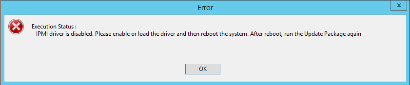
I was updating the BIOS on a couple of Dell PowerEdge R620’s today and was presented with an error I hadn’t heard of before:
IPMI driver is disabled. Please enable or load the driver and then reboot the system.
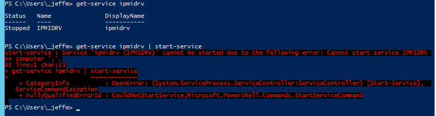
This was very odd. A little bit of searching showed that there should be an IPMI driver service running in Windows, so I checked that:
Service 'ipmidrv (IPMIDRV)' cannot be started due to the following error: Cannot start service IPMIDRV on computer '.
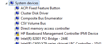
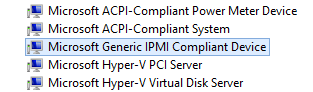
Knowing this was a driver, I went to look in Device Manager, and was quite surprised to find this IPMI driver listed:
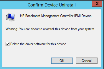
This is a Dell PowerEdge, I have no idea how this HP driver got installed – I’m not even convinced it wasn’t there prior to the other driver updates I was performing. In any case, this device wasn’t starting properly, and was preventing the service from starting. I uninstalled it and the driver:
Following this, the appropriate device appeared under “System Devices”:
Now I could start the service, and the BIOS update proceeded properly.
My Commvault disk library is nearing 90% capacity, which is a growing cause for concern. The disk library is provided by a Dell MD1400 with 12x6TB SAS drives, which was originally configured as a 10 disk RAID6 set with 2 hot spares (~45TB usable) on the PERC H830 card.
As an intermediate step before purchasing an additional disk shelf, I did the following to give a little breathing room.
Using the Dell Open Manage Server Administrator (OMSA), I located one of the hot spare drives and unassigned it.
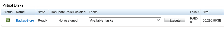
Still within OMSA, I chose the “Reconfigure” option on my Virtual Disk, keeping the RAID level at 6 but adding in the new available capacity.
Then I waited. It took 16 days for the reconfiguration to complete as the RAID6 parity was re-spread/calculated across the set. This left me with a ~50TB virtual disk.
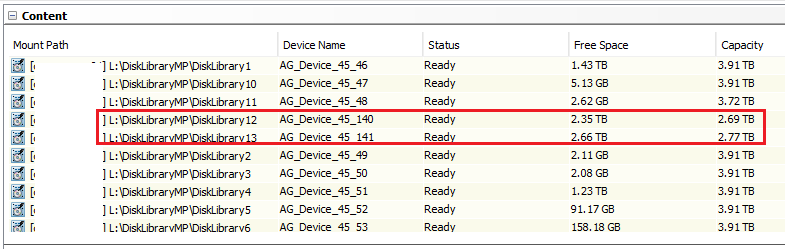
Within Disk Management, I carved the free space into two additional ~3TB volumes, which are mounted within a standard disk library path of L:\DiskLibrary. This size adheres to the recommendations given to us by our professional services partner.
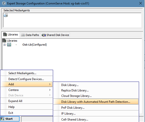
During the original configuration, we used Automated Mount Path Detection, to point to L:\DiskLibrary:
Due to this, the new mount paths were picked up automatically after about 15 minutes, and appeared within the list of mount paths under the library:
Checking the Disk Usage tab on the properties of the library dropped utilization down to 80%, and provided us some time to address the growing data concerns.
Since implementing CommVault Simpana, I have been receiving almost daily warnings of the following error (Event ID 5120) in my System log:
Cluster Shared Volume 'CSV2' ('CSV2') has entered a paused state because of '(c0000435)'. All I/O will temporarily be queued until a path to the volume is reestablished.
After some thorough investigation resolved a bunch of issues with cluster communication, this error continued to appear.
I was finally able to resolve this from happening by unregistering the EqualLogic VSS Hardware Provider, using this command:
The strange thing is, I had specifically set CommVault to use the CSV Shadow Copy Provider, with the setting “VSSProviders” on my clients. Despite this, there must have still been some VSS ties to the EQL provider.
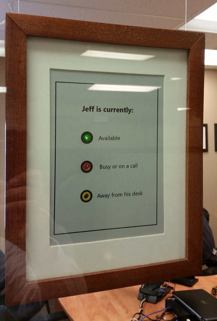
I use Microsoft Skype for Business (formerly Lync) extensively at work and utilize a headset while doing so. This combined with the fact that I recently moved into an office at work as opposed to a cubicle led me to wanting a physical indicator of my Skype presence so that people walking in could know my status.
I briefly investigated pre-packed indicator devices such as the Embrava Blynclight and BusyLight but decided that shipping costs were too much and it would be fun to make my own.
Shortly after I stumbled upon a post by Jon Gallant where he built his own using a Particle Photon and called it Beakn. This sounded like it would be exactly what I wanted, and so I set about building one.
Estimating the placement of the built-in LED
Step 1 – what will it look like?
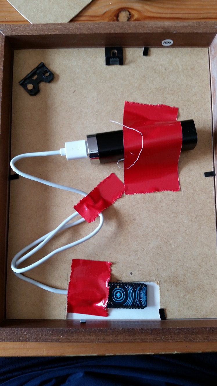
I thought about building it out of Lego, but my wife persuaded me that it wouldn’t be professional enough. I had seen a forum post where someone took the Embrava Blynclight and stuck it in a picture frame, and this really appealed to me.
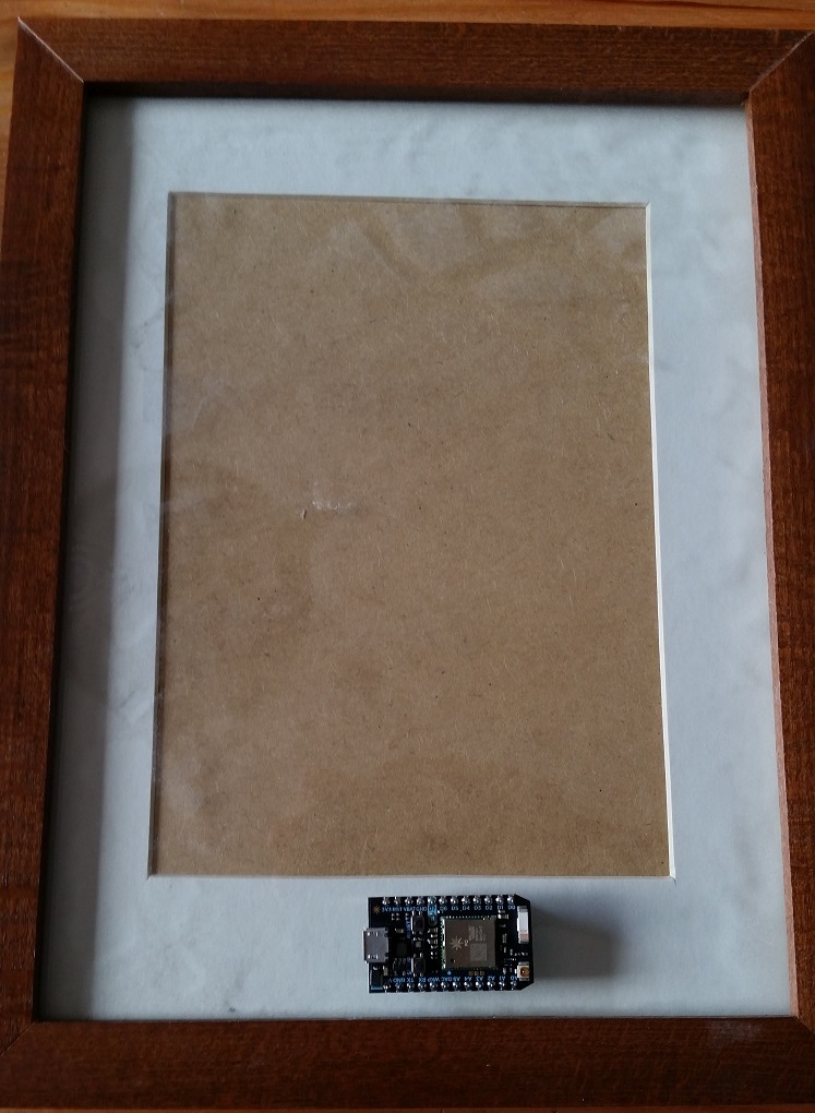
I bought a Photon, scrounged up a decent looking frame, and got ready.
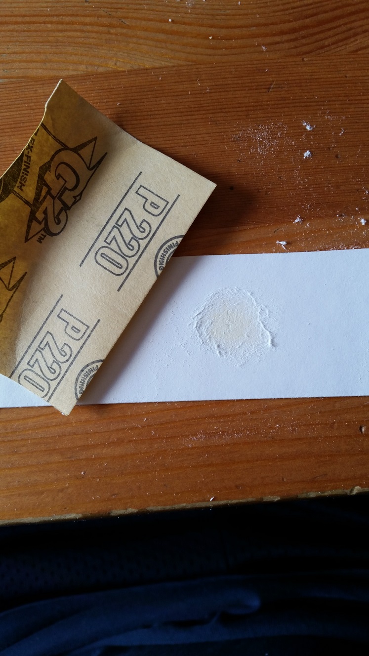
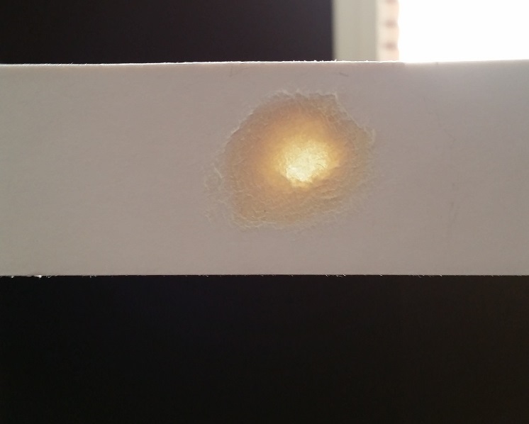
Step 2 – Build the prototype
I used sandpaper to thin out the mat so that the LED would shine through. I wasn’t very circular which may have had an impact on how unsatisfied I was with this design.
I had a small USB device charger that I used for my proto-type. A little bit of duct tape and I was ready to go.
Step 2a – Get the Photon on the network
I had a lot of trouble getting the Photon connected to my Wifi. It worked at home no problem, but when I brought it to work I couldn’t get it to connect. And then all of a sudden something happened where it wouldn’t boot at all but instead gave me SOS codes.
Through a support ticket with Particle I was finally able to get the device back online by flashing a new firmware. Then I discovered that the Photon uses non-standard ports for cloud communication rather than HTTP or HTTPs. Outbound traffic is restricted in my work network and so that was the source of connectivity issues.
Once all that was sorted, getting the code as documented by Jon Gallant was very easy and worked like a charm.
It’s alive! And apparently away from the keyboard.
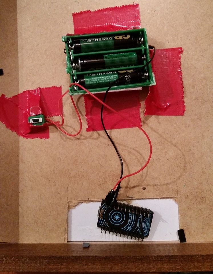
Step 3 – Better batteries
I shameless tore apart an old broken toy from the basement to make use of a battery pack. Unfortunately the best I could find was a 3xAAA pack with a power switch. More duct tape ensued and I wired positive (red) to the VIN pin and black to GND pin on the Photon.
This worked well at first, but when I took it to work and attempted to use it for real, the Photon would die after 10 minutes or so. I knew the batteries were brand new and not dead yet, so I posted a question to the Particle forums.
It turns out that 3xAAA is likely not providing enough voltage for the Photon when it’s constantly running it’s Wifi. I needed more power!
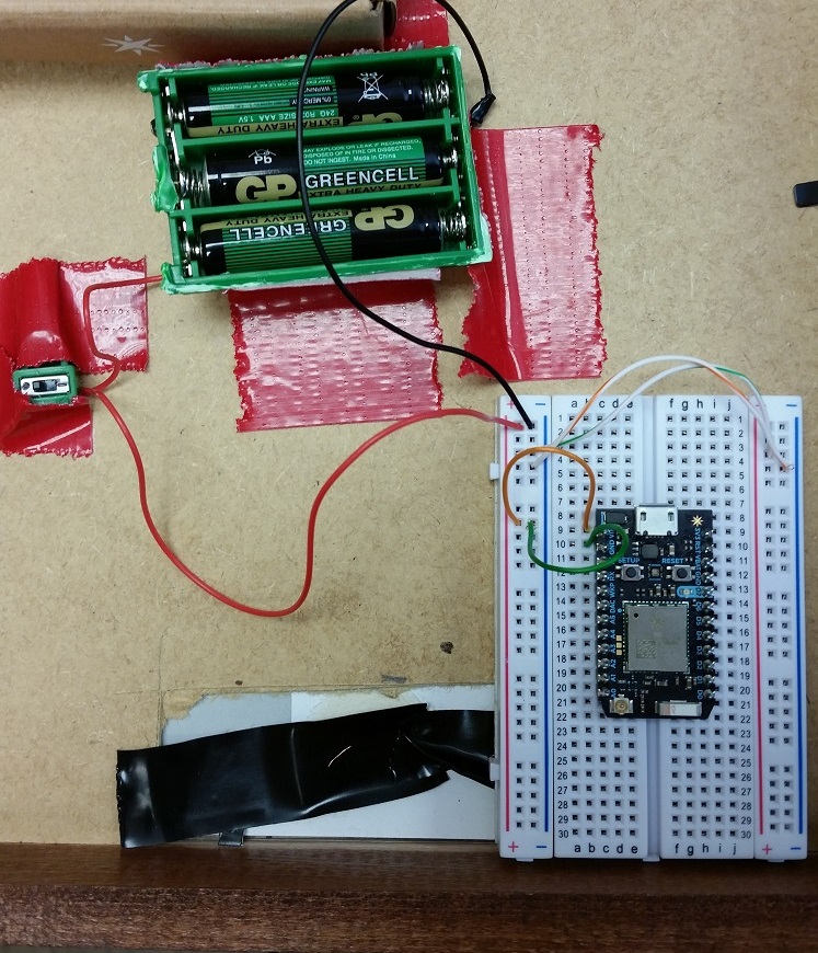
Step 4 – New batteries and changing LEDs
Through my prototype and AAA testing I had determined that the indicator light at the bottom of the frame just wasn’t going to do. It wasn’t bright enough, and didn’t match up well with the “Legend” that I planned to put in the actual frame.
This change let me use the breadboard that came with the Photon, and so I spent some time learning how to use it and the power rails. I highly recommend reading this Sparkfun tutorial.
Next I went back through some of Jon Gallant’s older posts and found his designs for individual LEDs. I decided I was going to put individual LEDs right in the middle of my legend, and again used a Sparkfun tutorial to learn about that.
Back into the basement to break more toys! I managed to find a good green and red LED but a poor quality yellow was all I could produce.
I went to Value Village and found a cheap toy that took 4xAA batteries and tore that apart for this project too.
I didn’t take good pictures of the final build process unfortunately, but it is fairly clear from this photo which I’ll walk through for those just learning like I am.
Power comes in from the batteries on the red wire to the positive rail on the breadboard. I have wires connecting the right-hand rail to ensure the circuit is complete there.
The next red wire on the left side goes from the power rail to the row with the VIN pin on the Photon. A black wire in the next row down takes GND pin from the Photon to the negative rail, completing the circuit.
On the other side, I sort of lost my color coordination because I got tired of stripping wires (I was using leftover 3 strand thermostat wire so all 3 colors were bundled together).
Pins 4, 5, and 6 on the Photon are wired to the positive ‘anode’ side of each LED. The negative cathode side is wired with the white cables, each going to a row with a resistor before completing on the negative power rail.
Looking at this photo now it almost seems like I have the resistor in the wrong place, as I thought it should be in between the positive source of the Photon pin, and the anode on the LED. But according to this it doesn’t really matter.
Here’s a close-up of the breadboard:
To get this setup to work, I had to modify the Beakn code because of the pins on the Photon I decided to use, and it didn’t have a status for “FreeIdle” when I locked my PC. The code I used in the cloud IDE is reproduced at the bottom of this post.
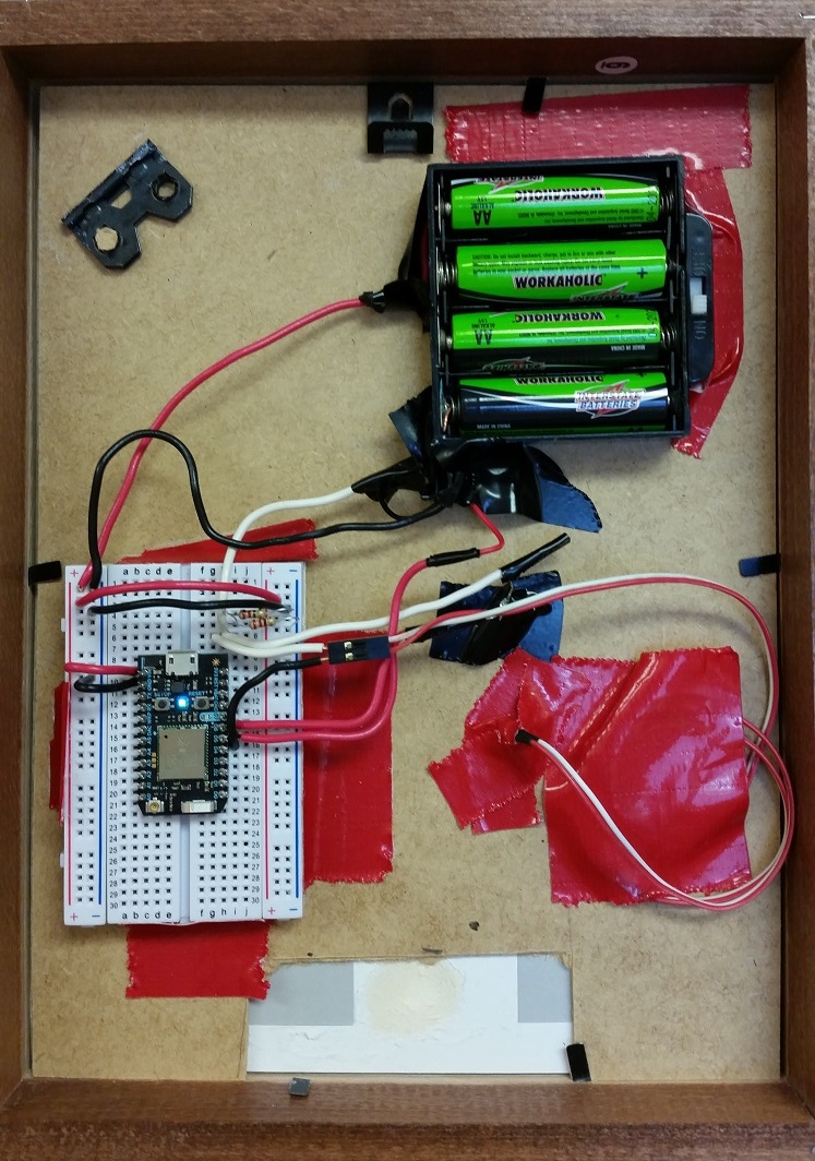
Once I had this all wired up, I used hooks and fishing wire, and hung it in my office window:
Overall I’m very happy with the results, but there’s room for improvement.
Step 5 – What’s next
Once I got this running, it only lasted 2 1/2 work days before the batteries died. Based on feedback from my particle forum post, I need a capacitor to smooth out the power draw and ideally a way to turn off the Wifi on the Photon and only check for status changes at intervals.
Neither of those are easily accomplished (because it’s hard to source a single capacitor and I have no soldering iron to break more toys with), so instead I’m going to use rechargeable batteries and attempt to build myself a solar charge mechanism using lawn lights. A future post will address that addition if I can ever get it to work.
Code:
int red = 5;
int yellow = 4;
int green = 6;
void setup()
{
  Spark.function("setStatus", setStatus);
  pinMode(red, OUTPUT);
  pinMode(yellow, OUTPUT);
  pinMode(green, OUTPUT);
  for(int i = 5; i <= 7; i++)
  {
      digitalWrite(i, HIGH);
      delay(250);
      digitalWrite(i, LOW);
      delay(250);
  }
  reset();
}
void loop()
{}
void reset()
{
  digitalWrite(red, LOW);
  digitalWrite(yellow, LOW);
  digitalWrite(green, LOW);
}
int setStatus(String status)
{
  reset();
  if(status == "Busy" || status == "DoNotDisturb"){
    digitalWrite(red, HIGH);
  }else if(status == "Away" || status == "TemporarilyAway" || status == "FreeIdle"){
    digitalWrite(yellow, HIGH);
  }else if (status == "Free"){
    digitalWrite(green, HIGH);
  }
  return 1;
}
### Note: I originally wrote this in 2012, and cannot even remember why I didn’t publish it. Hopefully it is useful as-is ###
I’m on a bit of a monitoring and benchmarking kick lately and have recently gathered some information on my environment regarding storage. I wanted to see a comparison of something low-end, my legacy storage, and our existing production storage.
I recently read this post by Brent Ozar on monitoring a SAN using CrystalDiskMark, as an easy way to get basic information. As Brent mentions, this isn’t an in depth benchmarking tool, but does give some idea of performance. Below are my results from the tests I performed. I couldn’t run CrystalDiskMark directly on my Hyper-V host since it’s Hyper-V Server 2008 R2 (native), so instead I ran it within the VM’s itself.
Details of CrystalDiskMark
A few interesting things I noticed here:
Sequential reads on our MD3220i are slower than our legacy MD3000 DAS
But sequential writes are over twice as fast, reaching the Ethernet limit of gigabit ISCSI
The 14 disk RAID10 LUN turned out to be faster than the 16 disk LUN on the MD3220i. Although CrystalDiskMark does 5 tests of each set, perhaps these numbers would still average closer together with more test.
Our 4x1TB RAID10 on the MD3000 was actually slower than a single laptop hard drive on some tests.
The biggest thing was the limit of ISCSI throughput. I wonder how much higher these values might be if we had fiber channel or were direct attached? Overall I’m not too concerned about it, because we don’t need a huge amount of throughput, but rather more IOPs.
With that in mind, I decided to check out SQLIO to see how things stack up there. Again I used a blog post from Brent Ozar to set this up.
I had a problem with interpreting the results, in that my test laptop was reporting IOPs of 1150, which is ridiculous. Upon further inspection, this was because I was using 2 threads with 8 I/O’s per thread. Reducing this down to just 1 thread with one I/O operation gave better results.
I still didn’t know whether I could trust it though, so I changed my test.bat to start a perfmon log at the same time, monitoring disk writes/sec, disk reads/sec and disk transfers/sec for the drive.
Then I compared the CUMULATIVE mark from SQLIO to the Max disk transfer/sec in perfmon.